I finally finished a small project I started about five years ago, that being a steno display for my keyboard. The idea is that my keyboard allows me to support stenography input using software like Plover, but I found it frustrating not to have better feedback, and my keyboard is programmable, so I thought I’d implement that. It was more work than I expected.
The basic idea of this was to use one of the fairly common character LCD displays sold by places like Adafruit or SparkFun. Several vendors make kits for adapting these to work with an I2C bus, using GPIO expanders. These turn out to be an awful idea for reasons I did not immediately realize.
My keyboard, an Ergodox EZ, runs QMK firmware, which is conveniently open source and user-modifiable. Also, it’s a split keyboard, so the left hand side of the keyboard talks to the right hand side over a fairly standard I2C/TWI bus, using a 4-conductor cable to provide voltage, ground, and two signal lines (clock and data). It was pretty easy to build something that could use existing drivers to talk to the LCD over this… and the results were sort of dismal, because it turns out that the protocol used to drive the display involves a lot of toggling of pins, and the GPIO adapters require large I2C transactions to set or clear each bit.
So I built my own prototype that interpreted a simpler protocol, so that instead of having to have multiple round trips of sending individual bit flips, I could just send single bytes that communicated the desired state change (such as displaying a character), and have a microcontroller handle the actual LCD display. This was fairly easy, and I did a prototype somewhere around 2016. It’s not pretty. Since then, I’ve periodically worked on trying to advance this.
Step one: Build a better controller
The first step was to try to design, and build, a kit for LCD controllers that would implement this protocol, and not be quite as much of a pain to work with. Making a design was easy. Prototyping it with wires was easy. Learning to use CAD software and generate files from that design which could be sent to a PCB producer was a little harder, but this summer, I finally got to the point of having a design for the board that I liked, and which worked. I used Eagle for this; I’m not a huge fan of Autodesk as a company, but the other packages I tried were a lot harder for me to work with successfully. The board/schematic files are available, too. I got three of the boards in the mail, put one together, and verified that my software worked. Here’s the base PCB:
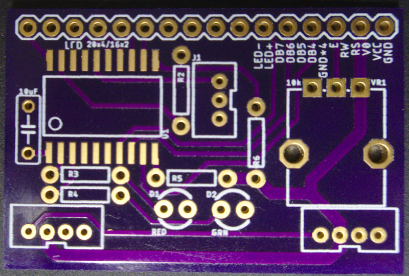
For software, I built my own library, using Peter Fleury’s LCD library for the underlying display communication. It’s just a project for Microchip’s IDE, and I don’t know whether it’ll work on its own, but the code should be easy enough to compile with any AVR-friendly toolchain. It lives at github.com/seebs/lcdctrl.
I haven’t got a working QMK build environment right now, so I don’t have a current version of the source, but the seebs/lcddisplay branch of my fork of qmk_firmware is still up on GitHub, and I’ll probably update it eventually.
Step two: Put the microcontroller somewhere
Then it came time to try to put the board, and the LCD, somewhere. Luckily, 3D printers have dropped enormously in price since I started this, so I got a 3D printer, and started trying to learn CAD software. Unfortunately, CAD software is a rough market; most of it is thousands of dollars and/or runs only on Windows. I found a free entry, FreeCAD, but the underlying library it uses has… let’s say “quirks”, such that changing any parameter of an early part of a design can break the entire rest of the design entirely, and fixing this appears to be really hard. So I went looking again, and found a thing called OpenSCAD, which offers a simplified programming language for describing 3D objects. This was a lot easier for me to work with. It took a couple of days to get a design fairly close to what I wanted:
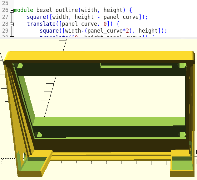
Printing this took about five hours, and it took several tries to get it right. The silliest part was that I kept running into sizing problems with the holes for the hex spacers that the board is supposed to be attached to. One weakness of OpenSCAD is that it can specify the outer radius (point to point distance) for a hexagonal shape, but not the face-to-face distance. It’s much easier to measure the face-to-face distance precisely, but more importantly (and I didn’t realize this for quite a while), the corners on the spacers are rounded, such that the dimensions of the distance between opposite corners, if used to size a hexagon, produce a hexagon whose opposite faces are noticably closer together than the opposite faces of the real objects. Oops.
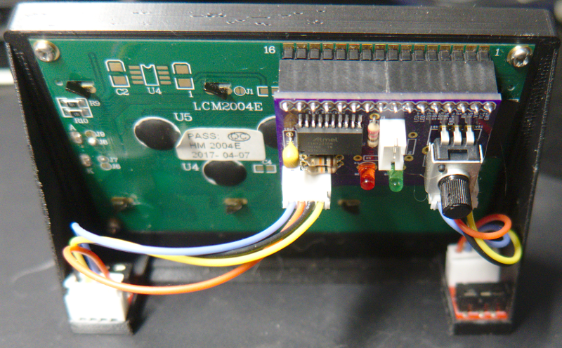
Once I had all those bits and pieces sorted out, it went together pretty nicely:
So now, if I put my keyboard into steno mode, the display updates to indicate that Plover is ready (even if the actual Plover software is not running on the desktop, admittedly):
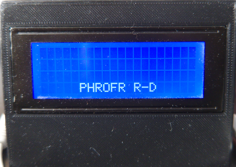
The yak is duly shaven. Time to actually try at all to learn steno, if I get around to it.